
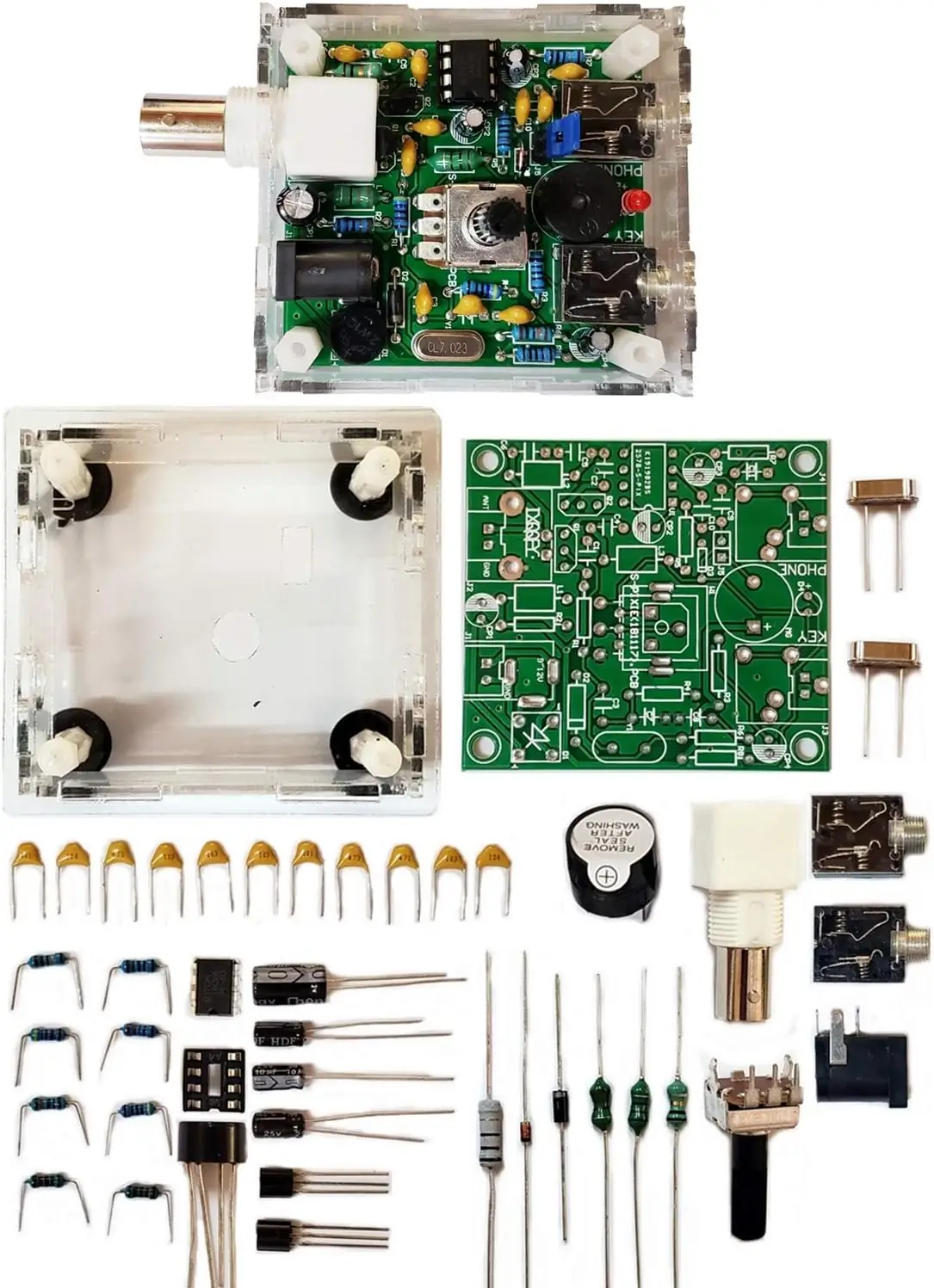
QRP Pixie Radio
When I saw this Pixie QRP radio for 10 bucks online, I thought it would be a fun little project to try out to get into the world of HF. I wasn’t expecting much from it, considering its price, but given that it would be some more soldering practice, I gave it a shot.
There were no documents included in the kit, so I had to do some research and reverse engineering to assemble it properly.
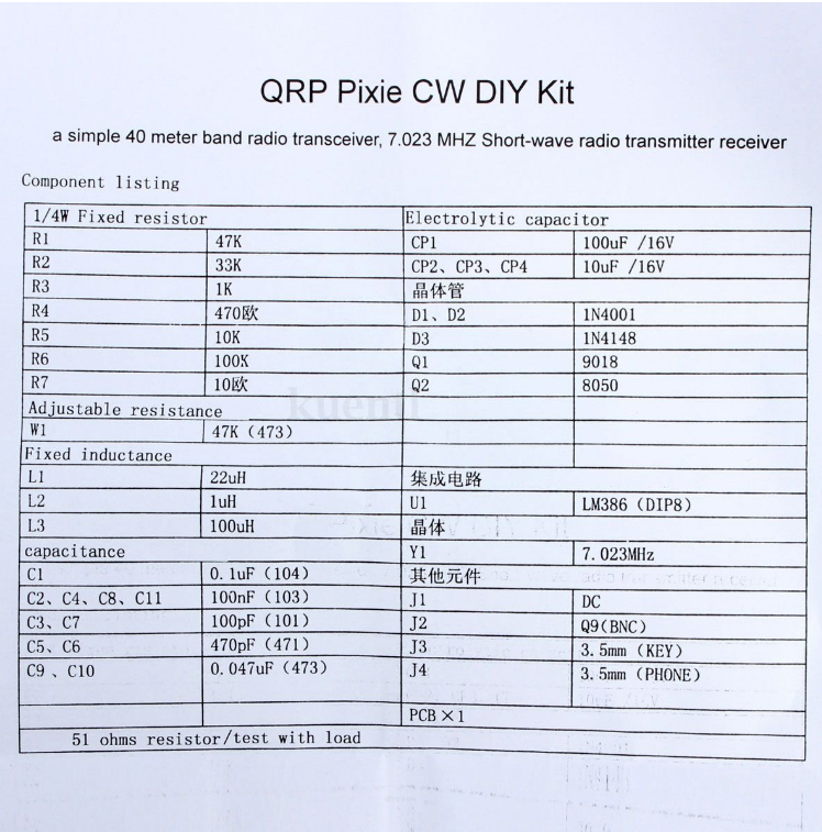
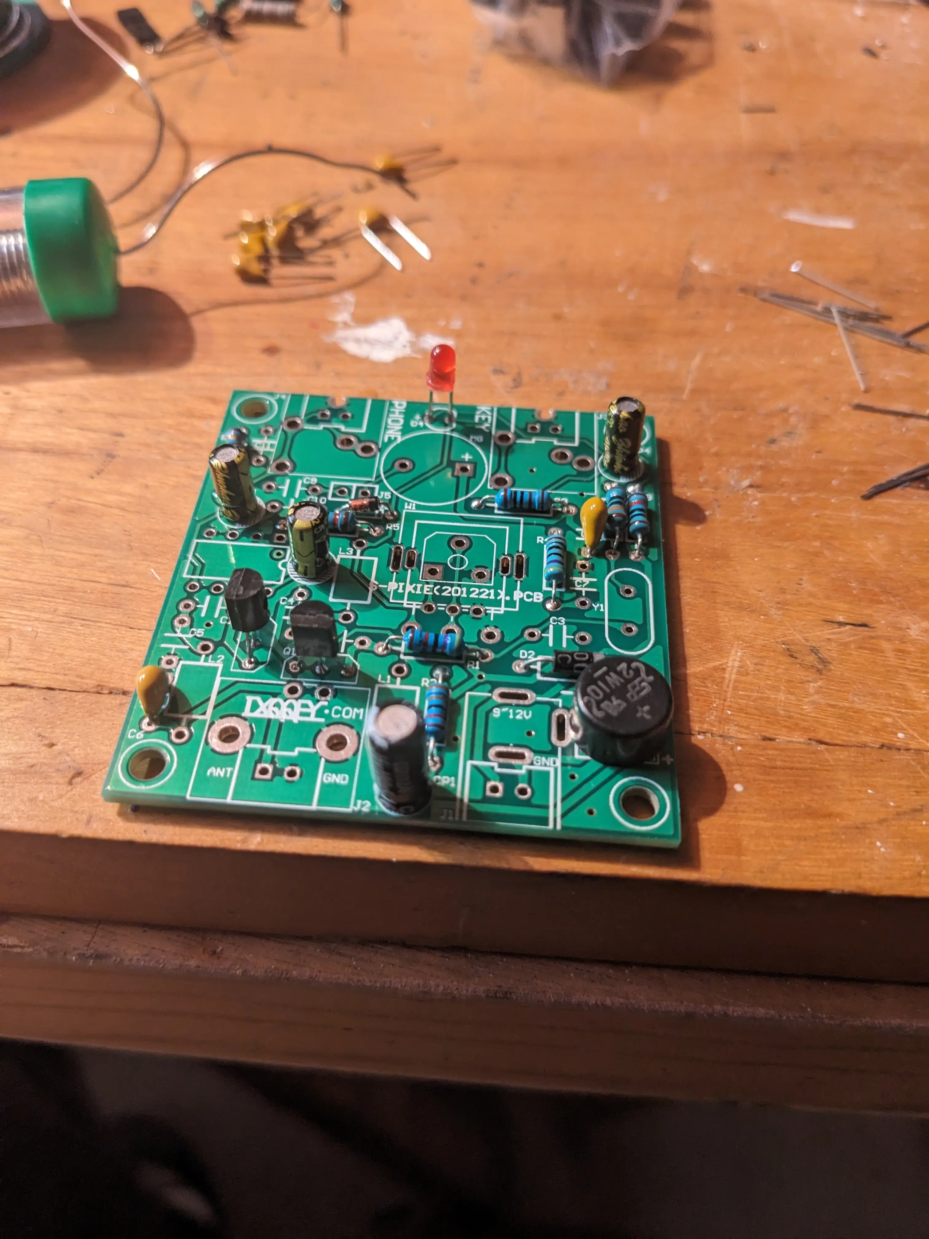
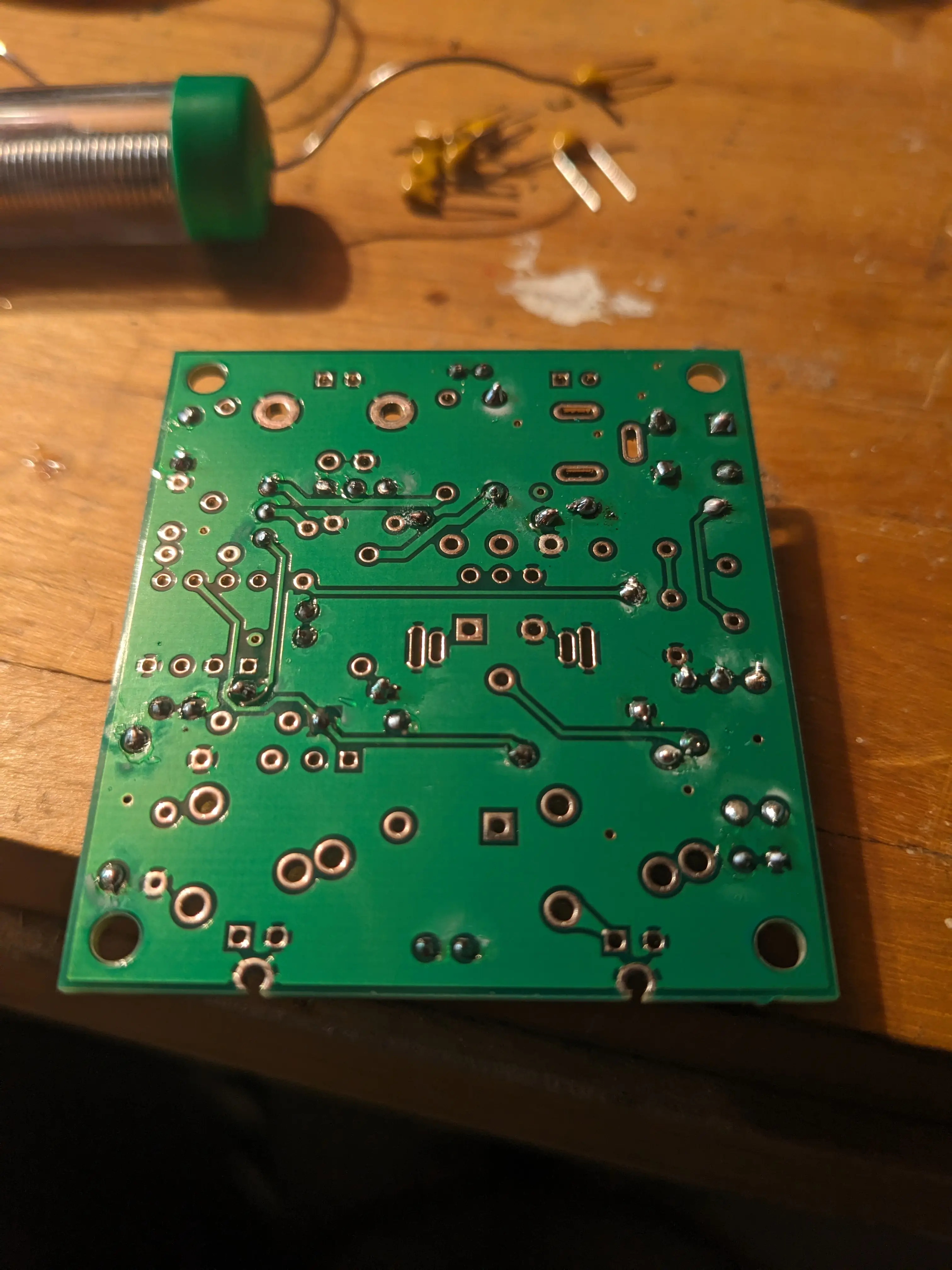
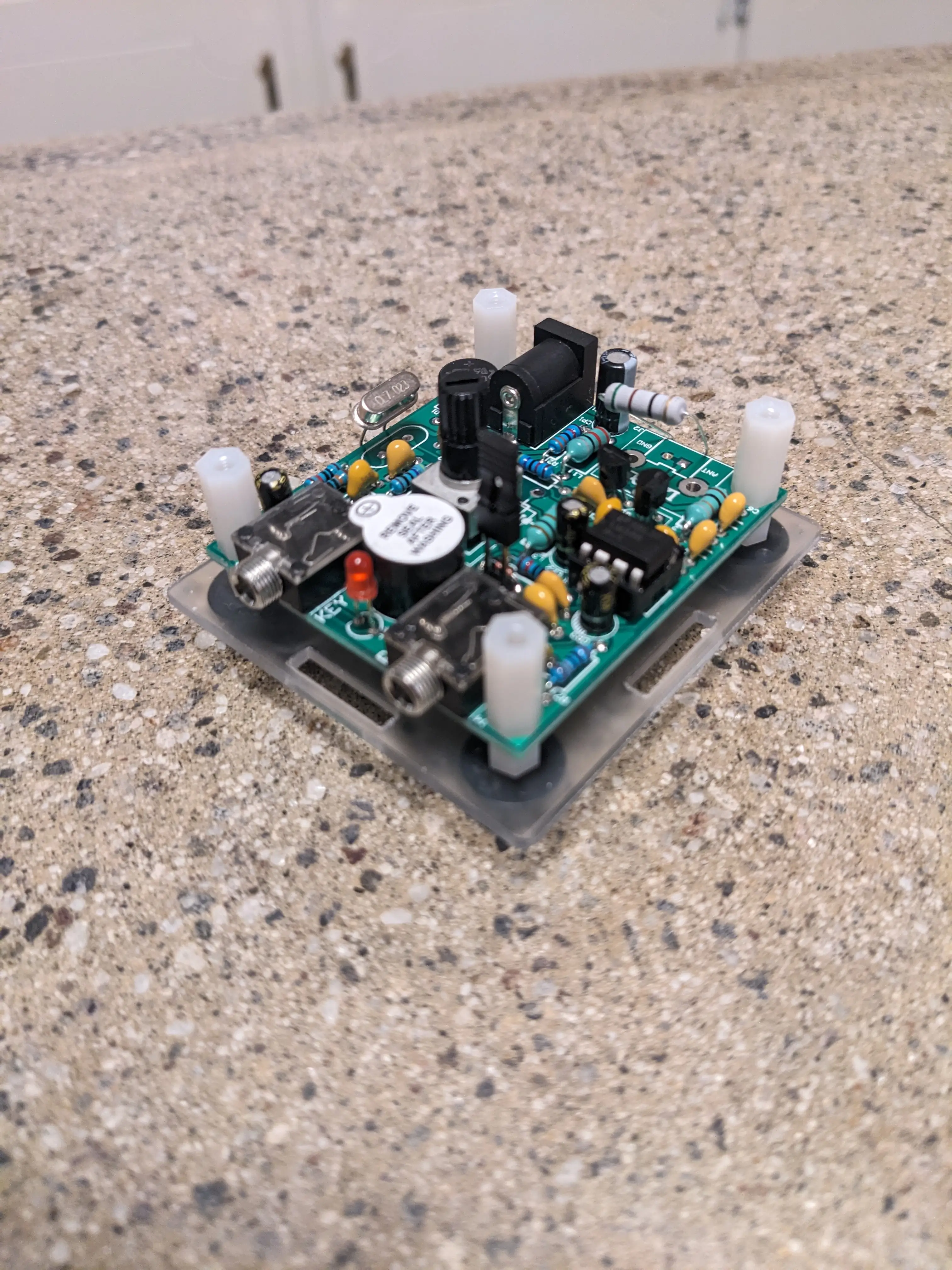
Once I had those two documents, I began the assembly process. First, I started with the resistors, which I used a multimeter on the ohm setting to verify the resistance of each component. I then matched each one to the paper and the corresponding number on the PCB silkscreen (R1, R2, …) and pushed them through and soldered their legs. This part definitely wasn’t my cleanest soldering, but it worked just fine.

Next, I moved on to the capacitors and diodes. Just like the resistors, I matched them with the document and pushed them through the appropriate holes on the board. I also figured that by leaving the legs straight instead of bending them over before soldering makes everything much cleaner looking.

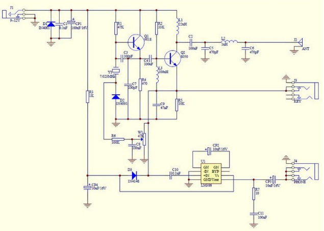
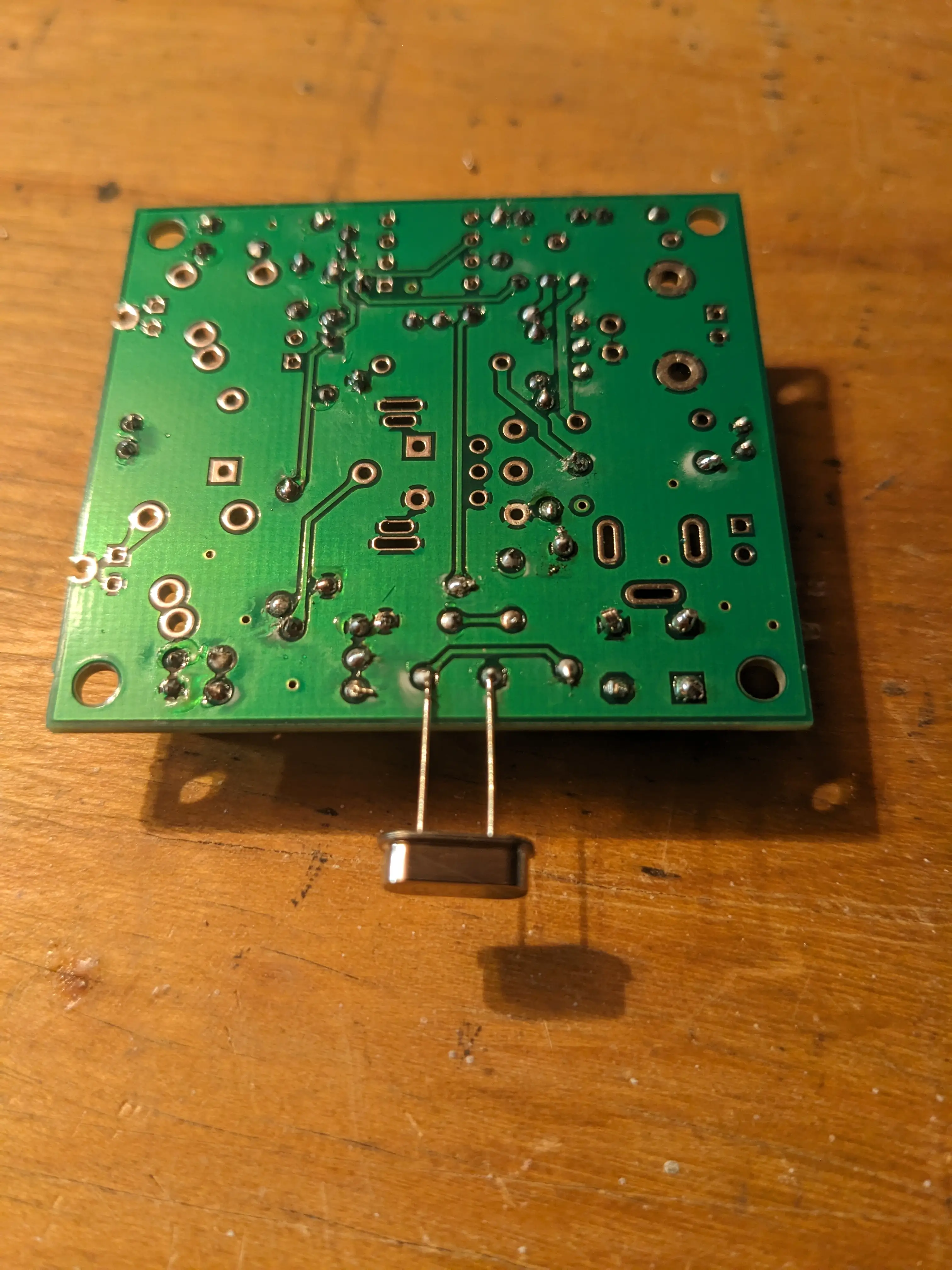
Then came the crystals- my kit came with two different options: 7.023MHz and 7.050MHz
These determine the TX frequency of the radio. The downside is that these make the device hard to tune and impossible to change your transmit frequency… Unless you follow VK3YE’s guide on fixing this problem
Now, if you are in the U.S. you probably want to solder in the 7.050MHz crystal, as that is a valid option for Technician and General class operators to perform CW transmissions. The other crystal is mainly used in European countries, and requires a higher privilege license class.
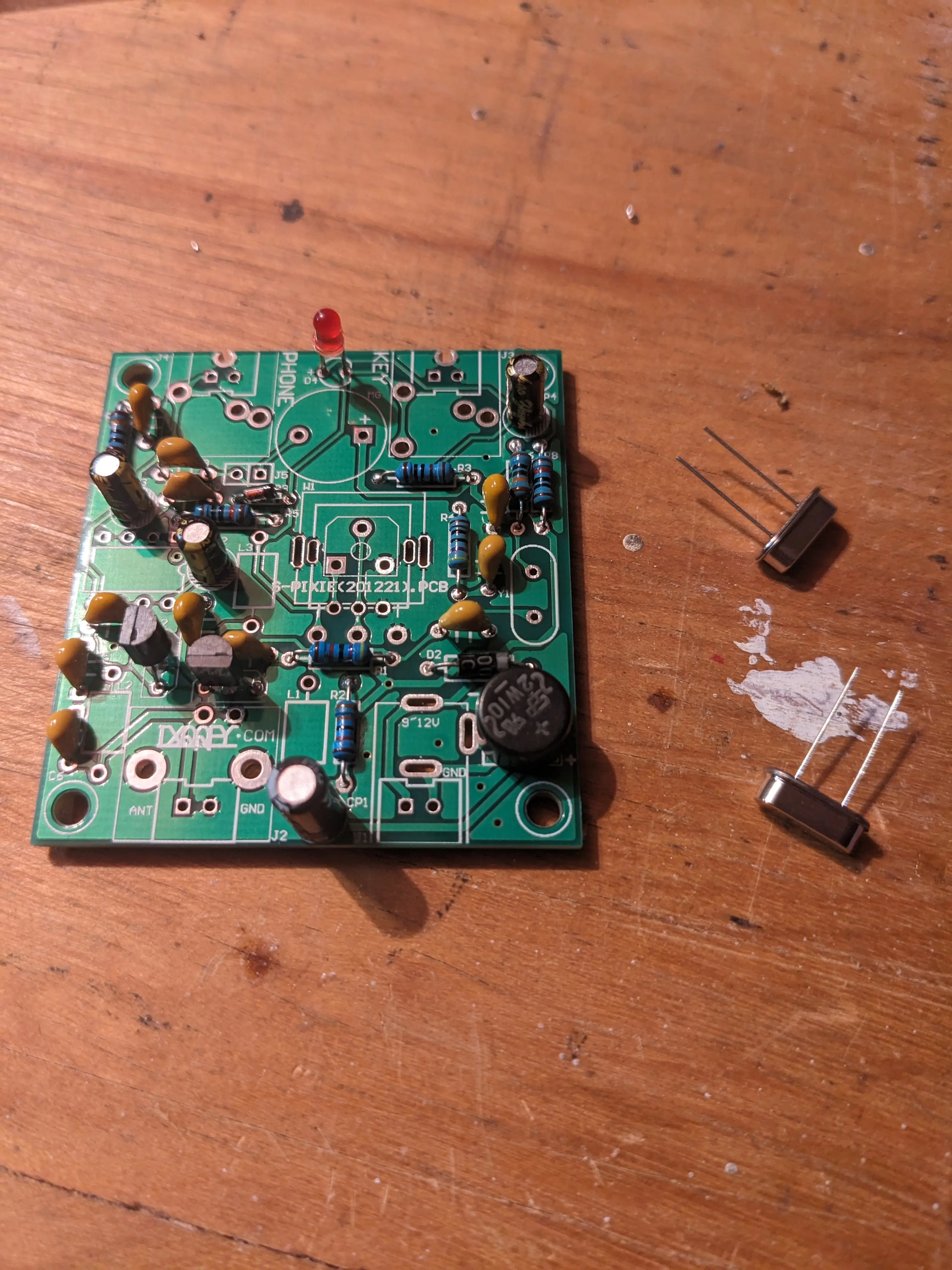
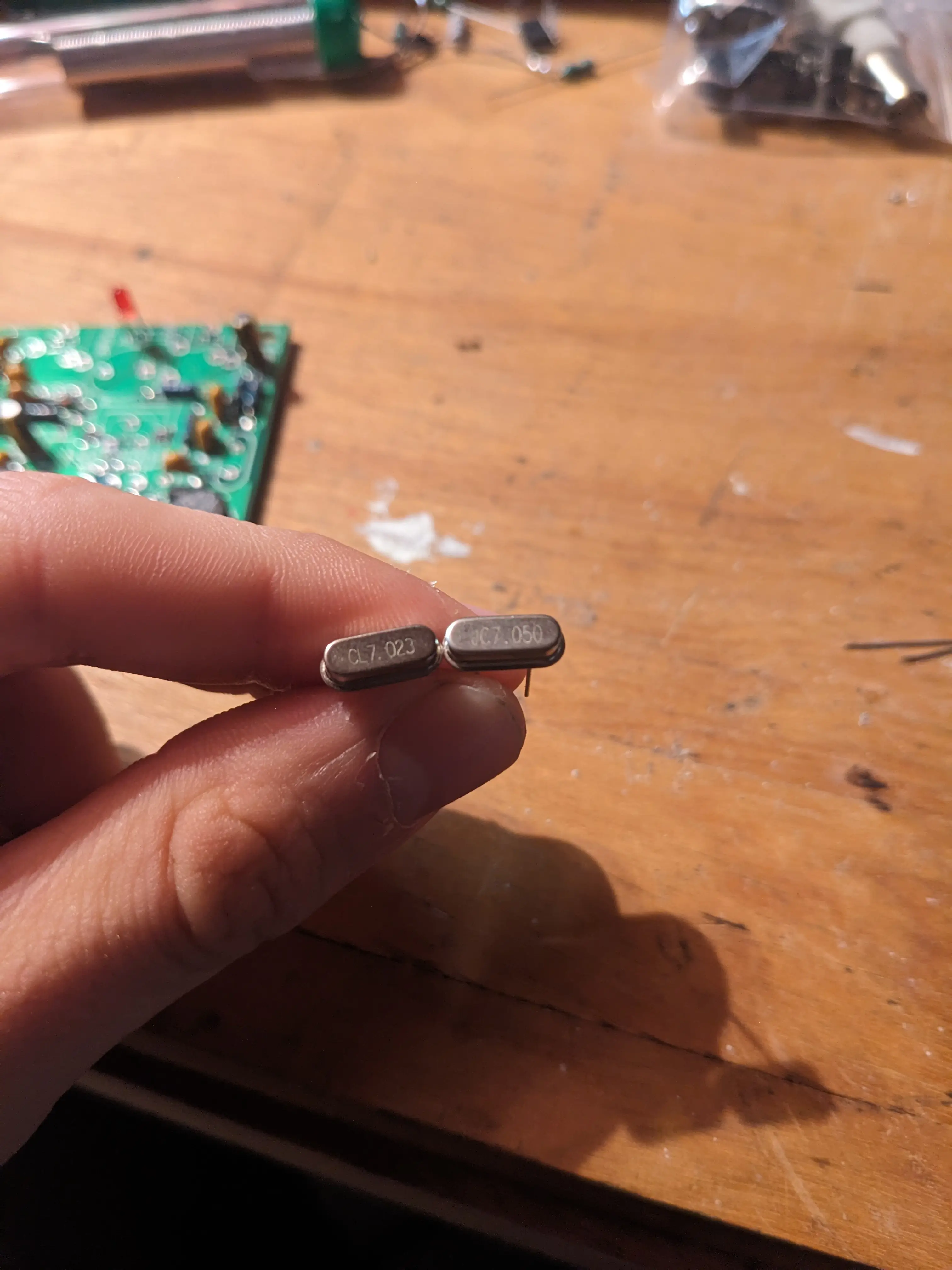
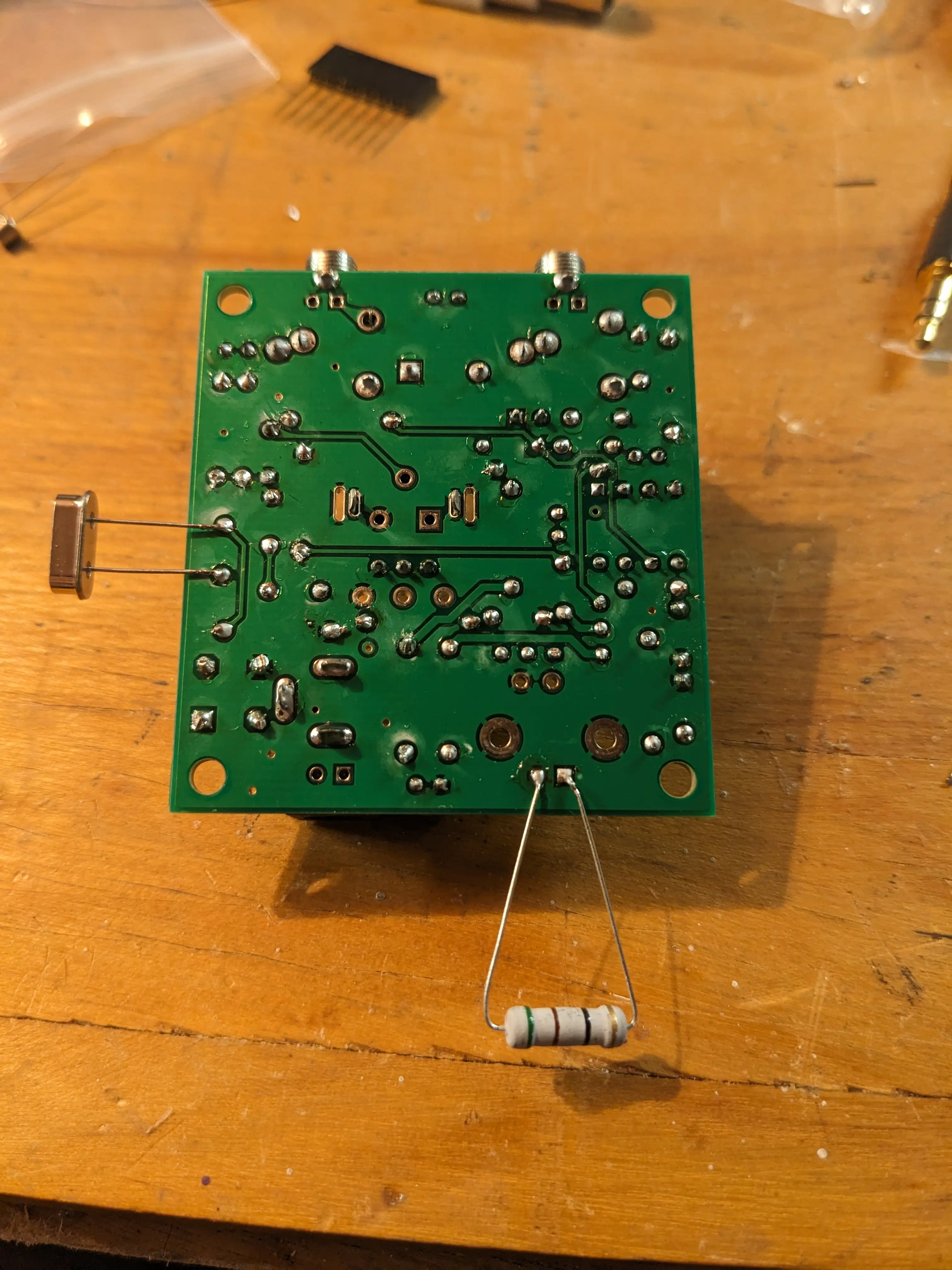
I chose the 7.050 MHz crystal, but installed it in a way that allows it to be easily hot-swapped if needed.
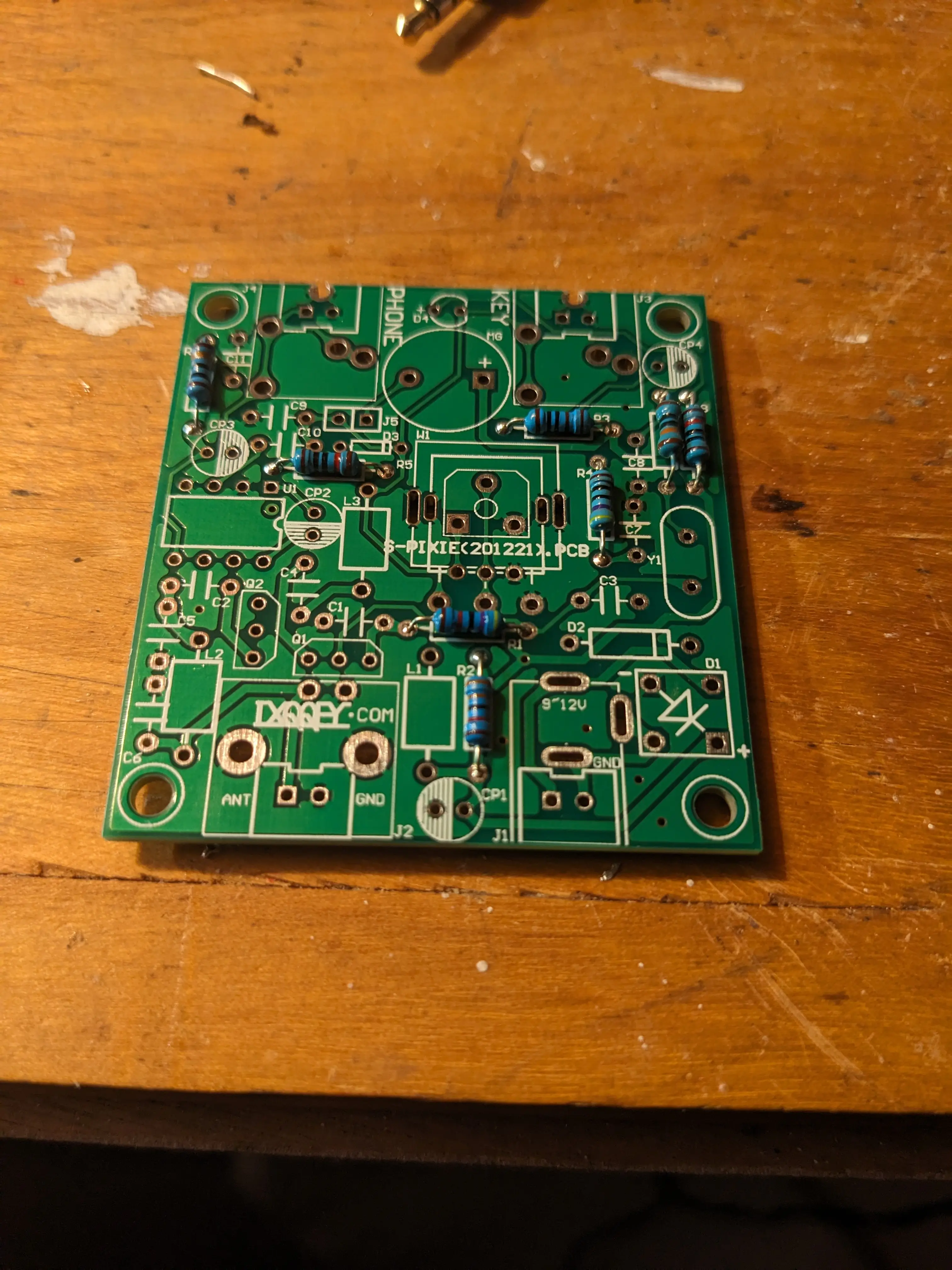
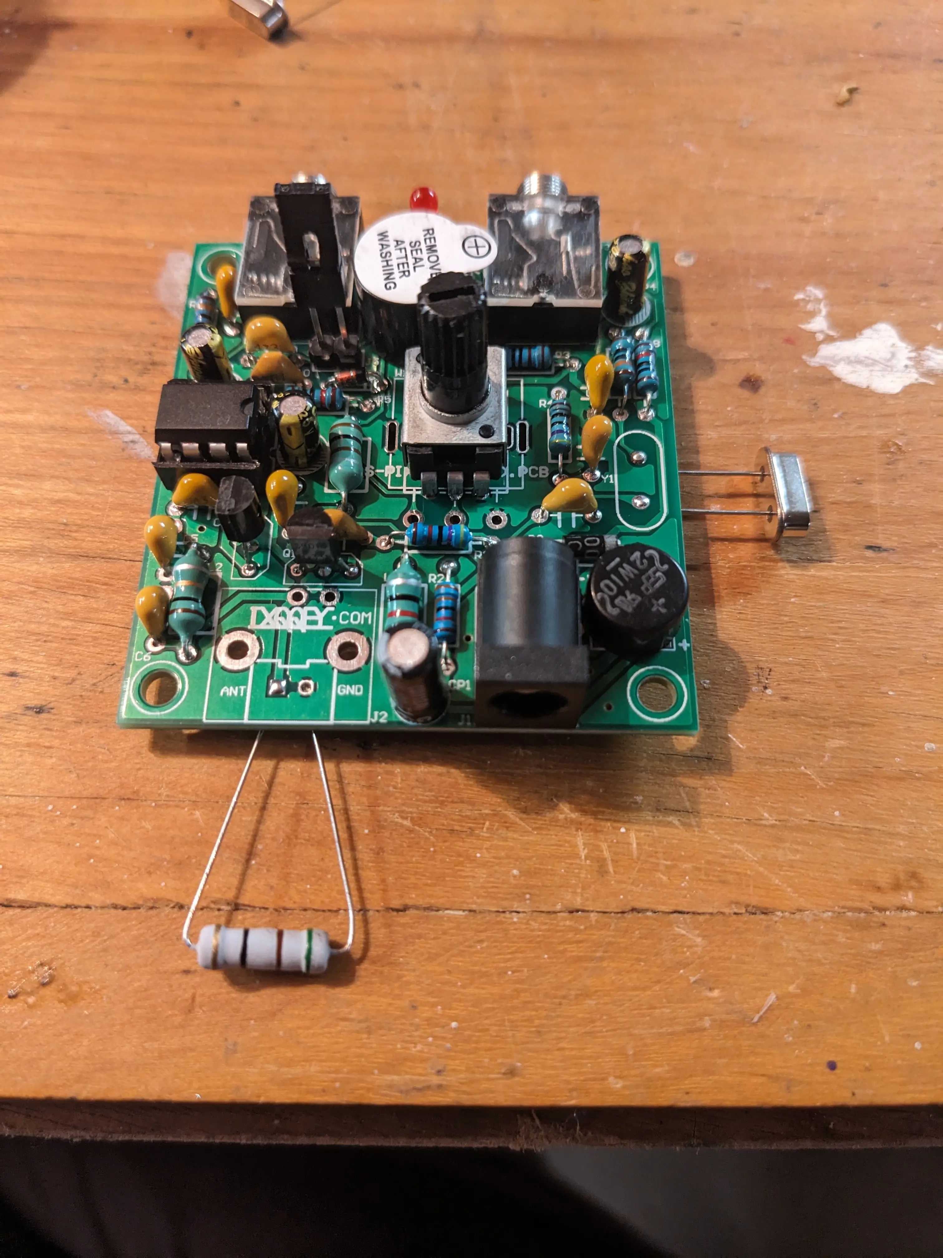
Another slightly confusing step was installing the inductors. I was having some difficulty finding and identifying the inductors by color codes or with measurement and finding the appropriate place to install them on the board. In the picture below, I labeled them to make installing them easier.

And to finish things up, I put all the other components on, like the audio jacks, power port, potentiometer, and buzzer. These were pretty self explanatory to install and took only a few minutes.
I also put on the 51 ohm, 1/2 watt dummy load resistor so I could test its TX functionality without accidentally transmitting across the globe.
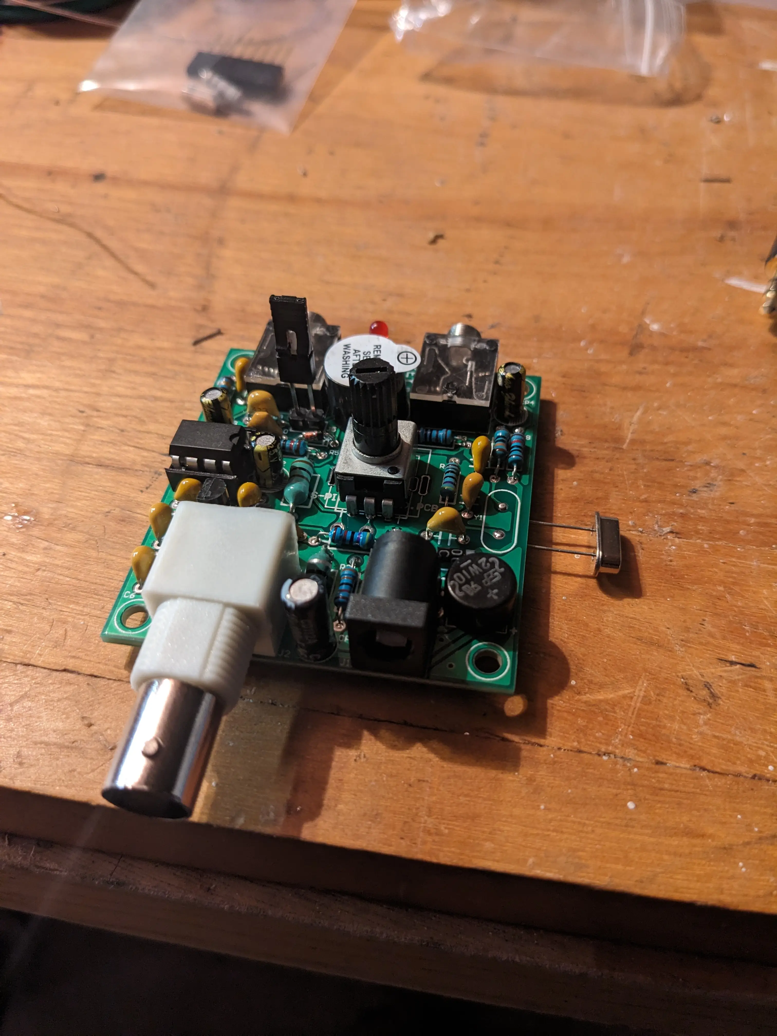
The last step was to add the acrylic case to protect everything. I personally think a metal shielded box would be a better fit, as this kit is definitely sensitive to interference from other electronics, power noise, AM broadcasts and other stuff. Nonetheless, I assembled the acrylic because it looks cool.
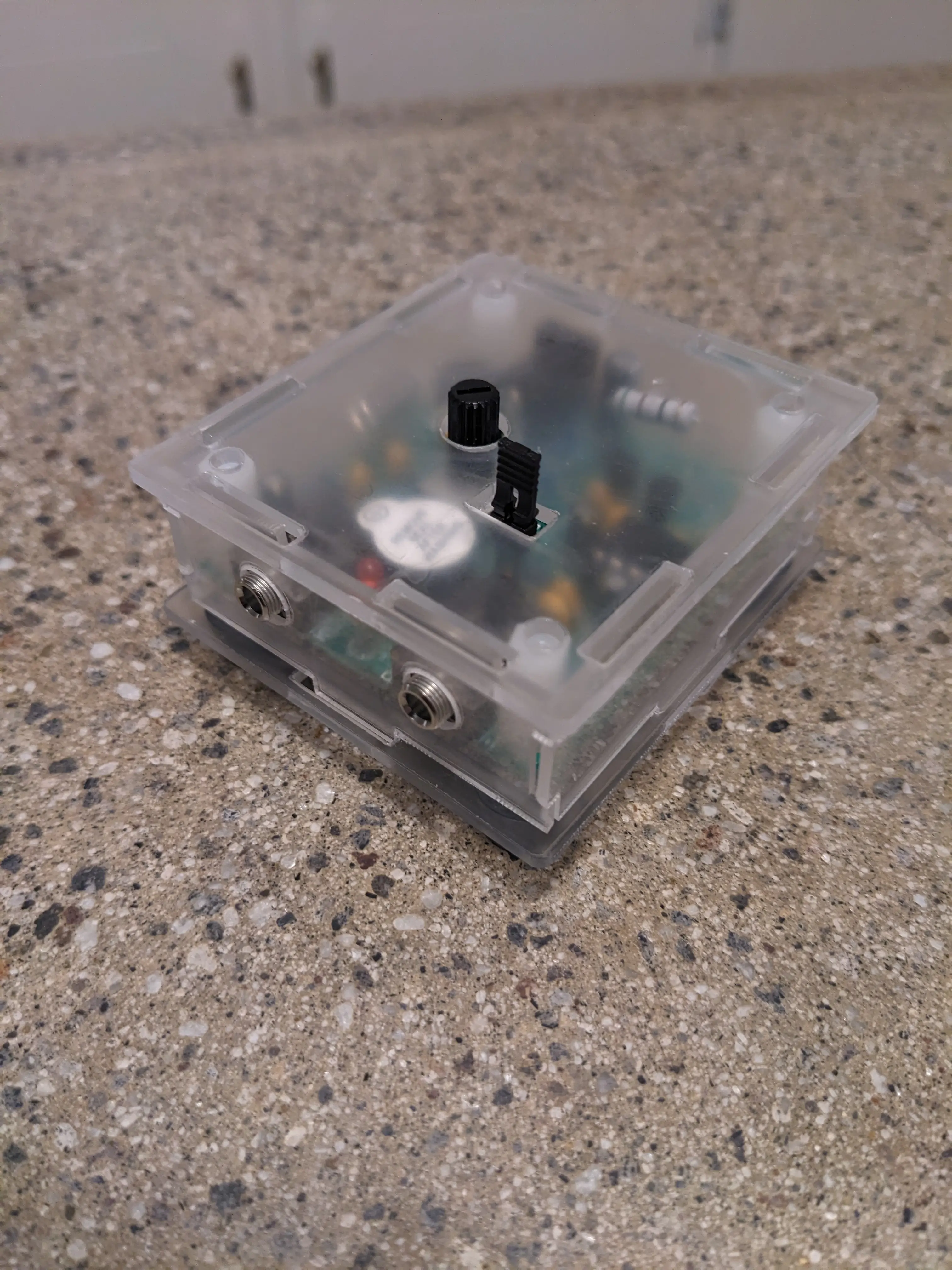
After this, it’s ready to go!
I found that in order to get any real results, you need either a proper 40m antenna (dipole, EFHW, etc) or (for rx anyways) a long wire connected to the antenna pin, and another wire connected to something grounded (copper water pipe, etc). After messing around, I was able to get a whole bunch of local AM interference, so I will need to do some mods or make a high pass filter for it to eliminate the AM broadcast.
This project would make a pretty cool beacon too. It will put out a few hundred mW which is perfect for a CW beacon.
I might make another post about optimizing the pixie to eliminate noise and make the RX filtering circuitry better.
73 de KC1VTJ
0
Views